Interesting Tech Projects
CNC
CNC Cutting Speeds
Sep 11th
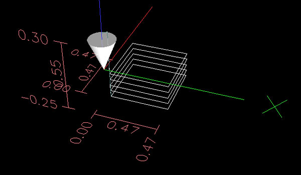
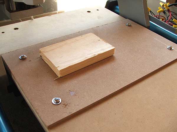
I am working on a design that basically involves cutting out a 4″ diameter disk from 1/4″ thick wood, with some shapes pocketed into the surface of the disk. I have been using 10 inches per minute (IPM) to cut through the Poplar and I had no clue if this is average, fast or slow. What I do know is that it is painful to watch.
At 10 IPM cutting out the design took 67 minutes. That is probably split 60%/40% with the majority on the pocketing. Too long for my liking. I decided to try and reduce the cutting time. First I increased the speed to 30IPM, which is nearly the maximum that my PC can go. Next I reduced the depth of the pockets from 0.15″ to 0.10″. This saves an extra pass.
The new time to cut? 20 minutes. Less than 1/3 of the original time. But that’s no good if the result is a ragged mess. Tonight I found out – there are more burrs on the wood, but the vertical edges look just as good as the ones cut at 10 IPM. So I will likely continue to use 30 IPM in the future.
My next aim is to split the cutting into two parts. The pocketing with a 0.0571″ end mill and the rest with a 1/8″ end mill. This should reduce the time even further.
Importing DXF Files Into Inkscape
Sep 7th
If you search around for ideas on how to import DXF files into Inkscape or convert DXF files to SVG files, there are a lot of results. But they mostly seem to be shareware or orphaned applications that haven’t been updated for years. However there is a simple, obvious (once you see it) and free solution to converting DXF files to SVG files (which Inkscape can load).
It’s called Open Office Draw.
Yes, that’s right. Open Office Draw can load a DXF file and save an SVG file. I’ve tried it and it worked – I was able to take a DXF file, convert to SVG, load into Inkscape, edit, save as DXF (see my other posting from a couple of days ago on this) then load into CamBam for CAM processing.
Using Inkscape for CNC Designs and DXFs
Sep 4th
Update: see this later post before following the instructions below.
I don’t care for most of the DXF editors available. They seem a bit clunky and not too friendly. But I do like Inkscape. Unfortunately it doesn’t export DXF files.
Here is a way of getting Inkscape 0.46 to export DXF files which can then be processed in a CAM program to generate g-code for a CNC machine.
Firstly install Inkscape 0.46. It must be this version.
Next go to this post on BobandEileen.com, right click on the link to “dxf_templates.py” and save it in C:\Program Files\Inkscape\share\extensions.
Next step is to go to another post on BobandEileen.com, right click on the two .py files (“simpletransform.py” and “better_dxf_outlines.py”) and save in the same place. Then do the same for “better_dxf_outlines.inx”.
Restart Inkscape.
Create a drawing and then move it to the bottom left corner of the page. This corner ends up being the origin. If you want your drawing centered on the origin then center it on the corner of the page.
Go to File -> Save As…
From the list of file types in the save dialog window choose “Better DXF Output (*.dxf)” and save the file.
Now open the DXF file in your favourite CAM program, such as CamBam.
Note that you may need to scale the drawing in your CAM program. Even though I had my drawings correctly sized in Inkscape, they seemed to be quite a bit bigger. If anyone knows how to solve that please post a comment.
EMC2 and CamBam Tab Test
Jul 18th
CamBam Plus has the option to automatically generate tabs. This is pretty nice and might make me change how I use fixtures to hold workpieces down. I’m starting to have concerns about the double-sided carpet tape, as I’ve seen the wood moving slightly during cutting.
I decided to create a simple test – cut a 0.5″ x 0.5″ square with tabs, in 1/4″ poplar. Also I cut the entire piece out so I could examine it and show it off to people (total size is 1″ x 1″).
CamBam Plus automatically generated the position of the tabs, but I needed to decide on the height and thickness. My first test using tabs with gears failed as the tabs were so thin they were non-existent. In this test they are 0.1″ wide and 0.07″ high. In order to saw the tabs later the outer profile cut has to be wide enough to get a tool in there. In this test it is 0.125″ wide.
The feedrate was 10IPM.
Here is the video – the final piece is shown at the end. In the EMC2 image you can clearly see the tabs at the bottom of the cube on each side. Sorry about the poor quality.
Making Gears
Jul 13th
Today it was time to give some new gear generation code a try. Using CamBam I created gcode for a gear with a 2″ pitch diameter, 18 teeth, 20 degree pressure angle and a diametral pitch of nine. I then cut a couple of them out.
The original plan was to work on precise cutting of two sides of an object. That idea failed so I had to eyeball it. Here is a video of my Fireball CNC V90 and EMC2 (running on Ubuntu Gutsy) in action:
The gears fit together nicely.
Cutting Holes with CNC
Jun 23rd
The next step in testing the CNC machine is to try cutting a hole. For this I needed thinner wood than the scrap pine I’ve been using. Home Depot sells small boards of oak and poplar so I picked up a piece of poplar. It’s 1/4″ thick.
I also needed to raise the sacrificial platform so the tip of the end mill can reach the bottom of the wood. To do that I just cut some more 16″ x 9″ pieces of 1/4″ MDF and stacked them (see the post on fixtures for more information and pictures on what I am talking about).
I used CamBam to draw a 0.5″ x 0.5″ square and then created a profile on the inside using my 1.45mm (0.0571″) end mill. CamBam showed me that I would have slightly rounded corners, but that’s ok. I decided to cut the profile in passes, increasing the depth by 0.05″ each time. This results in five passes to get to the bottom of the wood. Tedious, but better than stressing the end mill and Dremel.
I was afraid that the tip of the end mill might bind in the sticky double-sided carpet tape so I held on to the poplar with one hand and kept my finger on the power button with the other hand just in case. I was also afraid that the cube being cut might fly out as it came free.
It turned out pretty good. No sticky residue on the end mill and no gouging of the sacrifical platform. The cube in the center held in place during cutting and while I lifted the poplar. It came out when I removed the carpet tape.
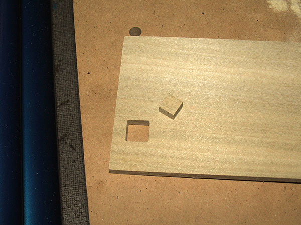
The cut is nice and clean with no burrs. I guess the carpet tape is a good method to continue using.
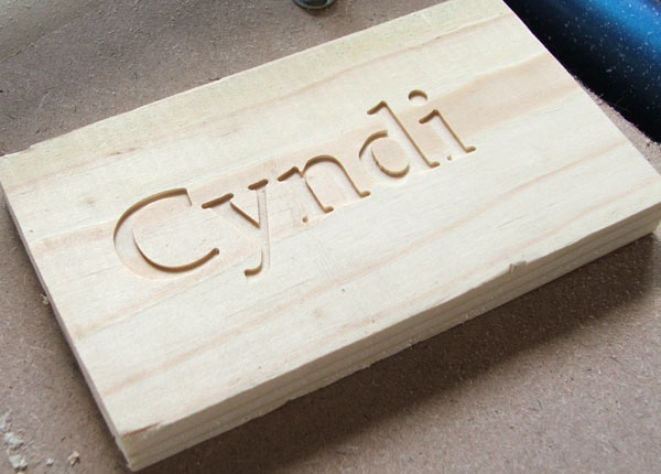
First Steps With CNC
Jun 22nd
Today I took my first steps cutting some scrap pine. I started off with a 2″ diameter circle then measured it. This is an acid test to check the CNC machine for accuracy and squareness. I used a 1.45mm four flute carbide end mill, 10″ per minute speed and cutting to 0.05″ deep.
Next I used CamBam to cut my wife’s name. That also went well, however even with the text 1.5″ high I was running into a limitation of the end mill. A small mill would have improved the detail.
Then I downloaded a DXF file of a horse and tried cutting that. Came out very nicely. The thin strip of wood left between the body and mane is thin enough to see light through it.
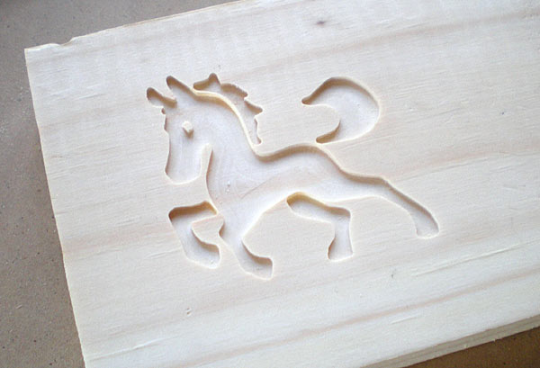
Here is a video shows the horse being made.
For all these I used the same end mill and cutting depth as I did for the circle.
Backlash Article
Jun 18th
I just found a nice article on backlash and how anti-backlash nuts work – Backlash in Lead Screws: What It is and What to do About It.
Creating Fixtures For a CNC Machine
Jun 14th
Fixtures are the method used to hold down workpieces, which are the items that will be cut. There are many different ways to do this and the following describes the method I have chosen.
Once my CNC machine was assembled, the surface looked like this:
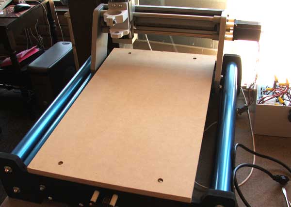
It is pretty much a piece of wood held down by four bolts. We can’t directly attach the workpiece to this surface however because when we cut all the way through the workpiece we will gouge the surface of the CNC machine. Therefore we need a sacrificial piece of wood in between. This sacrificial wood can be thrown away when it is no longer useful and replaced. In addition to using a method which allows the sacrificial wood to be easily installed and removed, it would be nice to allow different sizes of sacrificial wood.
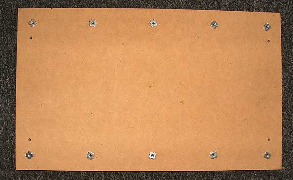
The solution I used for this is a grid of holes which allow bolts to be used. I decided to use a row of five bolt holes down each side of the CNC surface, regularly spaced apart. The four corner holes are 1.5″ in from each edge. The remaining holes are spaced 3 gaps of 6″ and 1 gap of 5.5″ apart along the longest edges.
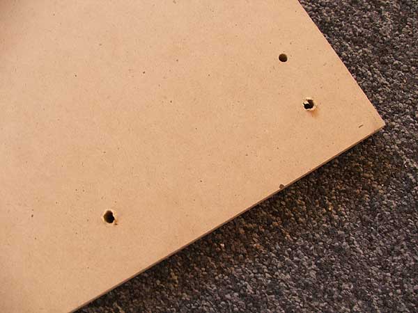
To drill the holes I used a 5/16″ wood spade bit. The next step is to attach 1/4″ – 20 x 5/16″ tee nuts. I achieved this by hammering them in. Attach the tee nuts to the underside of the CNC surface.
After reinstalling the CNC surface I cut a piece of sacrificial wood. I used scrap 1/4″ MDF from Home Depot. A sheet 4ft x 2ft cost me about $5. I cut the MDF down to 16″ x 9″ and drilled 5/16″ holes 1.5″ in from each edge (four holes in total). The MDF was then bolted down to the CNC surface using 1/4″ – 20 x 1″ bolts.
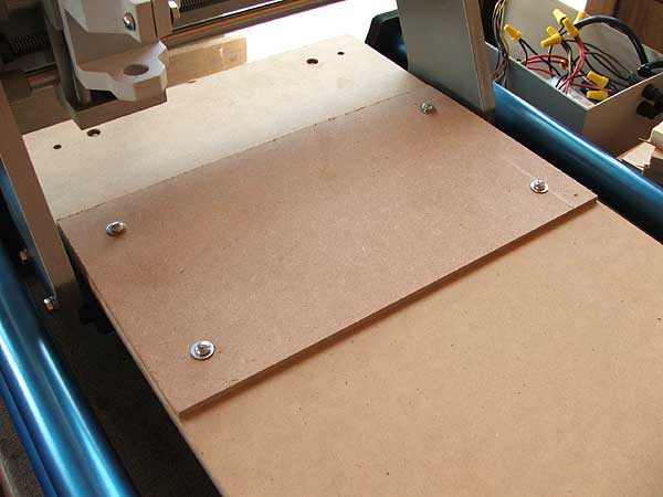
The final step was to use double-sided carpet table to fix the workpiece down onto the sacrificial wood.
Configuring EMC2 For Three Axis Stepper Motor Control
Apr 29th
There are many ways to configure EMC2, suiting many different uses. But perhaps the most common is control of three stepper motors. This post describes the process I went through to configure EMC2 for my CNC machine, which is a Fireball CNC V90. These steps may not match exactly your needs, but perhaps it will help as a starting point for further exploration.
It assumed that you have managed to get EMC2 installed and have run the latency tests with no overruns. If you are seeing overruns then try the hints on the EMC2 Troubleshooting page.
When you see ‘$’ in this post, it represents the user prompt. Don’t type it, only type the commands that follow. Replace “andy” with your own user name.
First we need to know how many steps per second your PC can generate. To do that we run the kernel latency test:
$ cd /usr/realtime*/testsuite/kern/latency

$ sudo ./run
The test will output a set of numbers. Use the PC to browse the web, play music and check email for a few minutes. However don’t run EMC2. Stop the test and note the largest value in the “ovl max” column. In my case it was 92,191. Values over 100,000 may not give good performance. In general the larger the value the worst CNC performance will be. There are some hints in the EMC2 wiki on how to lower this value.
92,191 means 92.191us (us = microseconds). Between the PC at the stepper motor is a driver chip, such as the SLA7078MR. This chip has some delays that are required for each edge. By reading the datasheet for the driver chip we can find out what this is, and for the SLA7078MR it is 12us. If you don’t know or not sure, I would suggest you pick a value similar to this and err on the side of caution by making the value a bit larger.
So we have 93us (rounded up) + 12us = 105us = 105,000ns (ns = nanoseconds). This is the BASE_PERIOD (more on that in a bit).
Therefore the maximum step rate for my PC is 1 / (105us x 2) = 4,762 steps per second.
It’s possible to tweak the steplen, stepspace, dirsetup and dirhold values to achieve better results than this, but that topic is outside the scope of this post. See the EMC2 documentation for details.
We next need to calculate how many steps are needed to move one inch with 1/4 microstepping. If you wish to use a different microstepping configuration or millimeters then adjust the following calculations accordingly.
My stepper motors require 200 pulses per revolution. This is a very common amount. With 1/4 microstepping it will take 200 x 4 = 800 steps per revolution.
On the X and Y axis of my machine the lead screw has 10 turns per inch but it is has two starts, which makes it 5 turns per inch. This is a pitch of 1 / 5 = 0.2 inches.
Therefore 0.20in / 800 steps per rev = 0.00025in per step.
Therefore 1 / 0.00025in = 4000 steps per inch. 4000 becomes the INPUT_SCALE value for X and Y.
The maximum speed is 4762 steps per second / 4000 = 1.1905in per second = 71.43in per minute. 1.1905 is the MAX_VELOCITY for X and Y.
On the Z axis of my machine the lead screw has 12 turns per inch. This is a pitch of 0.0833in.
Therefore 0.0833in / 800 steps per rev = 0.000104166in per step.
Therefore 1 / 0.000104166in = 9600 steps per inch. 9600 becomes the INPUT_SCALE value for Z.
The maximum speed is 4762 steps per second / 9600 = 0.4960416667in per second = 29.7625in per minute. 0.4960416667 is the MAX_VELOCITY for Z.
We now have all the information needed to complete the configuration of EMC2. First we must copy the example configuration files and then customize them.
$ mkdir /home/andy/emc2/

$ cp /etc/emc2/sample-configs/stepper /home/andy/emc2/

$ sudo chown andy:andy /home/andy/emc2/*
Rename all values to remove “dpkg-new” from the end of the file names. Then:
$ cd /home/andy/emc2

$ mv stepper_inch.ini mymachine_inch.ini

$ nano -w mymachine_inch.ini
Scroll down to the BASE_PERIOD line and set it to the value calculated in nanoseconds. In my case it is 105000.
Scroll down to the trajectory planner and set the MAX_VELOCITY value to the largest MAX_VELOCITY value of all the axis. In my example it is 1.1905.
Scroll down to the section that configures the first axis (X) and set the INPUT_SCALE to the value calculated. In my example it is 4000. Set the MAX_VELOCITY and STEPGEN_MAXVEL to the MAX_VELOCITY value for the axis. In this example it is 1.1905.
Repeat for the Y and then Z axis.
The final step is to edit standard_pinout.hal to match the pinout of your controller board. The important section in the file looks something like:
linksp Xstep => parport.0.pin-03-out

linksp Xdir  => parport.0.pin-02-out

linksp Ystep => parport.0.pin-05-out

linksp Ydir  => parport.0.pin-04-out

linksp Zstep => parport.0.pin-07-out

linksp Zdir  => parport.0.pin-06-out
Simply change the “03”, “02”, etc. values to match the pin numbers used by your board. “Xstep” means the step input for the X axis.
Now run EMC2 using:
$ emc /home/andy/emc2/mymachine_inch.ini
Set the jog rate to the maximum for each axis in turn and jog the axis. It is possible that the axis may stall or lose steps. This is because the value we calculated is a theoretical maximum. However it gives you a starting point to reduce the speed of the axis until it works reliably. To do this lower the jog speed slightly until it works then using the INPUT_SCALE work out a new value for the number of steps per axis. For example, assuming we had to lower the jog speed to 60.000 in per minute on the X axis:
60.000 in per minute / 60 = 1.000 in per second. 1.000 in per second x 4000 steps per inch (INPUT_SCALE) = 4000 steps per second
Now a new value for BASE_PERIOD can be calculated:
1 / 4000 steps per inch / 2 = 125,000ns
Edit mymachine_inch.ini and set the new BASE_PERIOD value. Note that this will lower the speed of all axis. Recalculate the MAX_VELOCITY value for all axis and update the configuration file with the new values. Then retest.
I found that on my PC it can operate at the theoretical maximum speed without problems. I hope this helps you configure EMC2 for your machine.