Interesting Tech Projects
Posts tagged axis
First Steps With EMC2 and AXIS
Apr 28th
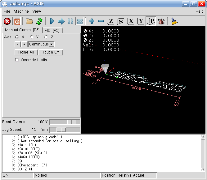
This post describes the first steps after running EMC2 with the AXIS interface for the first time. To start choose AXIS -> Sim from the menu after starting EMC2.
Starting the attached CNC machine (in this case a simulation) requires two steps. First the emergency stop (e-stop) must be turned off. Then power must be turned on.
To turn off the e-stop click on the toolbar button that looks like a red circle with an “X” in it.
To turn on the machine click on the toolbar power button (to the right of the e-stop button).
At this point most of the user interface should now be enabled. Until you have a real e-stop button connected to your machine, you can click on the toolbar E-stop button at any time to stop the machine.
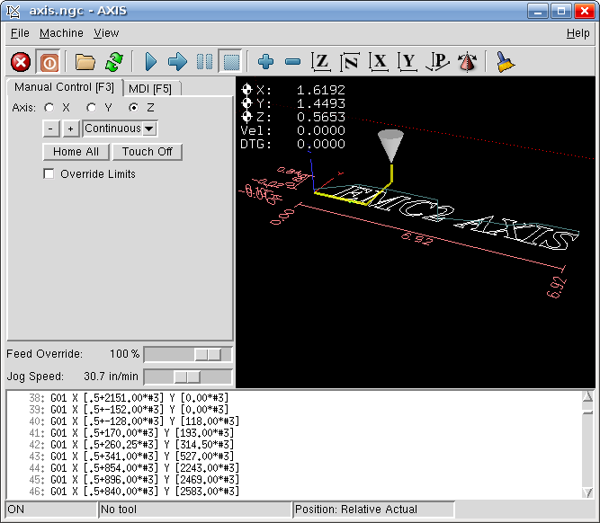
Drag the “Jog Speed” slider to something like 30 in/min. Now to jog the axis. Make sure the “Manual” tab is selected.
- Select one of the axis X, Y or Z
- Choose “Continuous” from the drop down list
- Click on the “+” and “-” buttons to jog. Watch the cone move in the display
- Now try a different axis
The display also shows the current X, Y and Z position in inches of the tip of the cone, which represents the tool (drill bit).
Now try clicking on the execution toolbar button, represented by a blue triangle. EMC2 will execute the loaded g-code file, which outlines some text. Watch the cone move as the code is executed. There are additional toolbar buttons to pause, step through and stop execution.
To zoom in on the display move the mouse over the display and use the scroll wheel on your mouse. Alternatively press the right mouse button and drag.
To pan the display move the mouse over the display, press the left mouse button and drag.
To rotate the display move the mouse over the display, press the scroll wheel and drag.
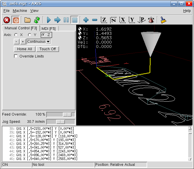
There are also toolbar buttons to control this operation. In addition there is a toolbar button representing a broom. Clicking on this will clear the lines showing the path that the tool has made.
Next click on the “MDI” tab to access the command line interface. In the MDI Command box enter:
G00 X0 Y0 Z0
Watch the cone move back to the origin in the display. Now try the following and watch the cone move:
G00 X1

G00 Y2

G00 Z0.5
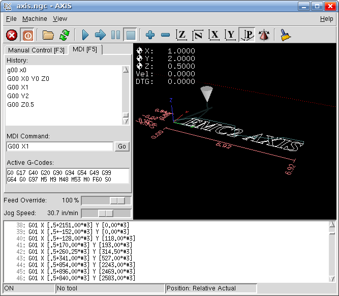
At this point the cone should be at 1, 2, 0.5. Any number of axis can be moved at once, and the number after the axis name is the absolute position. For example:
G00 X2 Y2.5

G00 X0 Z0.1

G00 X0 Y0 Z0
G00 means move the tool as quickly as possible. This is only used when not cutting, as it is typically too fast to move the bit through a material.
Note that all the numbers used in this tutorial are in inches, however it is easily possible to configure EMC2 and AXIS to use millimeters. In which case G00 X1 would move along the X axis one millimeter.