Interesting Tech Projects
Part Design Tools and Workflow
After spending quite some time trying different pieces of software I have come up with a collection and a workflow that I think will fit my needs.
I wanted to be able to accurately design parts in 3D, see how the parts will fit together to make sure they are right, and produce traditional engineering drawings of the parts, if possible. Also it is necessary once a part has been designed to be able to convert it into toolpaths, which is the path that a drill bit would move along to make the part. The toolpaths are represented using g-code which can be processed by EMC2 to move the stepper motors. Another requirement was to use free software where possible to try and keep costs down.
I start with Alibre Design Xpress. This is an excellent 3D design program that is also free. However free comes with a price, that is limitations. The key limitations are a limited number of export options and limited number of parts in an assembly. An assembly is a collection of parts fitted together to build something. However with enough perseverance these limitations can be overcome. In Design Xpress I created a simple test part that contains two holes for bolts:
Creating this 2D profile is very quick and easy. The holes are 0.174″ in diameter, which should be big enough for a #8 bolt. Next step is to extrude the 2D profile into a 3D part:
The part can be rotated and viewed from any angle. I decided to make the part 0.250″ thick. At this point Design Xpress can produce various numbers regarding the part, depending on the material it is made of. Choosing “Wood – southern pine” resulted in:
Volume = 1.480147117 in³
Mass = 1.576592260E-2 kg
Surface Area = 1.453202145E1 in²
Pretty interesting.
The software only allows five unique parts in an assembly, unless you register then it is 10. However this is quite a severe limitation in my opinion. Fortunately there is a way around this. Alibre has written an add-on called 3D Publisher for Google Sketchup that allows parts to be exported in Google’s Sketchup format. It’s not a requirement that the parts be uploaded to Google’s 3D Warehouse. Instead the exported parts can be saved to your hard drive. The following screenshot shows an assembly of two of the test parts along with size #8 bolts and nuts. The exact bolts are ANSI PHN, CRSHD TYPE II, B18.6.3, .164-36 UNF, 0.75, which gives an indication of the accuracy expected from designing parts and assembling them.
Again, this assembly can be rotated and the parts can be made transparent, along with plenty of other options. There is even a free add-on for Google Sketchup that provides a ray tracer. Assembling two parts confirmed my intention that the holes will line up.
With a few mouse clicks Design Xpress can convert the 3D part into traditional engineering drawing:
This can be printed out, emailed, etc. and provides all the measurement details for someone else to reproduce the part without having access to electronic files. The drawing can also be exported as a DXF (without the annotations), which is needed for the next step.
I found an excellent application to generate toolpaths for a part called CamBam. It takes a DXF file and provides an easy to use user interface in which you can select which items are profiled, drilled, pocketed, etc. Once the DXF file is loaded into CamBam all the unneeded views are deleted to leave the original 2D profile. For this part I added a 2.5D profile operation to cut the outline of the shape and two sprial drill operations for the holes:
Cam Bam then generates the g-code which can be loaded in the AXIS interface in EMC2:
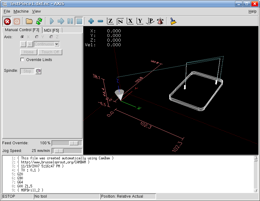
This process may seem convoluted, and it requires both Windows and Linux, but all the software can be obtained for free and is high quality. I haven’t completed my CNC machine yet, but I can watch the part being made in the AXIS interface without having the motors connected. I would expect that all the software will work in a Virtual Machine in Linux, however note that Design Xpress requires a lot of RAM to run (300Mb I believe).
| Print article | This entry was posted by Andy on November 19, 2007 at 10:24 pm, and is filed under CNC, Linux. Follow any responses to this post through RSS 2.0. Both comments and pings are currently closed. |

Using Alibre Design for Multi-color and Multi-material 3D Printing Part II
about 11 years ago - 1 comment
Previously I wrote about my little utility that allows exporting properly positioned STLs from Alibre Design so they can be imported into a slicing program for multi-color printing. This is fine for use with the RepRapPro slicer but perhaps not with other slicers. Slic3r is a very popular, fast and flexible slicing program and now…

Ray Tracing (Rendering) with Alibre Design PE
about 11 years ago - Comments Off on Ray Tracing (Rendering) with Alibre Design PE
The Professional and Expert versions of Alibre Design come with a ray tracer called Keyshot but the Personal Edition of Alibre Design does not. However it is easily possible to use the free and very powerful Blender to generate ray traces of your 3D models. First you must design the parts in Alibre Design and…

Using Alibre Design for Multi-color and Multi-material 3D Printing
about 11 years ago - 2 comments
When you wish to print out a part on a 3D printer the workflow is simple – design the part, export to STL and print it. This is fine when you are only printing with a single material or color. Becoming increasingly popular and affordable are 3D printers that support printing with two or three…
Radio Controlled Aircraft for Stroke Victims
about 12 years ago - Comments Off on Radio Controlled Aircraft for Stroke Victims
This post introduces my open source radio control project. It allows an RC aircraft to be controlled from a Wii Nunchuk, i.e. with one hand! Videos will be posted when they are available but so far it is working great in the flight simulator and with a stationary aircraft. All documentation, source files and binary…
The Progress of Linux
about 13 years ago - 2 comments
Back in 1998 I tried installing RedHat 6 on a spare PC. When the desktop loaded it was, ummm, wobbly. I then spent the best part of the next two weeks fighing with X configuration files setting obscure items such as front and back porches in a futile attempt to stabilize the display so it…
Installing Ubuntu Netbook Remix on an Acer Aspire One
about 15 years ago - 4 comments
The Acer Aspire One is a pretty nice netbook – for a reasonable price you get 1Gb RAM, 160Gb hard drive, 1024 x 600 screen and 5 1/2 hours of battery life. However it comes with Windows XP or Linpus, which is a customized Linux distribution from Acer. Neither of these options appealed to me.…
Low Cost and Free CAD Programs
about 16 years ago - Comments Off on Low Cost and Free CAD Programs
I have stumbled across a large list of low cost and free CAD programs, mostly for Windows however. It seems there are many good choices in the list and I will try out a couple in the next day or two. Bookmark to: Hide Sites
How To Install EMC2 on Unbuntu 7.10 Gutsy From Scratch
about 16 years ago - 9 comments
April 2008 – Update – I’ve modified the instructions so that EMC2 can now be run as a user. April 2008 – Update – Fixed some mistakes. The following instructions will describe how to install the latest version of EMC2/LinuxCNC in Ubuntu 7.10 Gutsy Gibbon. Why would you want to do this? You would do…
Windows XP and Stepper Motors
about 16 years ago - 2 comments
My first test after assembling the board was to connect one motor to each axis in turn and test using Windows XP SP2 and Mach3. The test involved going to the motor tuning section and pressing the up and down arrows. On the X and Y axis it was clear that steps were being lost.…
Testing EMC2/LinuxCNC on Ubuntu 7.10 Gutsy
about 16 years ago - 1 comment
I just completed the first test of running EMC2/LinuxCNC on Ubuntu with the HobbyCNC board. I connected a motor to the X-axis and started EMC2 with the “Axis” interface. I then told it to execute the default G-code file it loads with. Lo and behold the motor started spinning! I then moved the motor to…
Comments are closed.
about 16 years ago
Thank you for this great tutorial,
I am currently using and evaluating a number of CAD/CAM packages and Alibre and CamBam are added to my list after reading this.
Rob