Interesting Tech Projects
Scripting Polyholes in Alibre Design
3D printing by using layers of melted plastic filament, such as used by RepRap printers, causes small holes (less than 15mm in diameter) to end up smaller than the designed size. To compensate for this people create designs with larger holes so they shrink to the right size. It’s not an ideal solution – how much do they need to be increased by? What if you later want to send the same design to a commercial printing service that is more accurate?
The RepRap developer Nophead examined this issue and came up with a simple way to design holes that print at the right size regardless of the printing method. He called them polyholes.
In short the solution is to approximate the hole with a polygon and increase it’s size slightly.
Creating these polyholes in a CAD package is tedious. The size has to be calculated and the number of sides varies with the hole size. ADScript has this functionality baked right in. Here is an example python script:
# use millimeters for all values
Units.Current = UnitTypes.Millimeters

# test block dimensions
length = 15
width = 10
depth = 3
# size of test holes
diameter = 3

# create a new part, get the XY plane and create a sketch on the plane
PolyholeTest = Part("PolyholeTest")
XYPlane = PolyholeTest.GetPlane("XY-Plane")
Base = PolyholeTest.AddSketch("Base", XYPlane)

# draw the part outline
Base.AddPolyline([0, 0, length, 0, length, width, 0, width, 0, 0], False)
# draw a regular hole
Base.AddCircle(length / 3, width / 2, diameter, False)
# draw a polyhole
Base.AddPolyhole(length / 3 * 2, width / 2, diameter, False)
# extrude the sketch into a part
PolyholeTest.AddExtrudeBoss("Block", Base, depth, False)

# save and export to STL for printing
PolyholeTest.Save("C:\Users\Andy\Desktop")
PolyholeTest.ExportSTL("C:\Users\Andy\Desktop\PolyholeTest.stl")
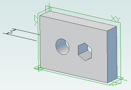
When this script is run it produces the following test part with the regular hole on the left and the polyhole on the right:
To rotate the part simply change the plane used, perhaps to “ZX-Plane”, and run the script again.
| Print article | This entry was posted by Andy on April 6, 2013 at 12:00 am, and is filed under 3D Printing, Computer Aided Design, Software Engineering. Follow any responses to this post through RSS 2.0. Both comments and pings are currently closed. |
Comments are closed.


about 11 years ago
Great article, I’ve been following your Alibre articles and love them. Thanks
about 6 years ago
Hey Andy,
I used your script to get started. Very helpful.
Happy New Year!!!