BritishIdeas
Interesting Tech Projects
Interesting Tech Projects

Sep 16th
Faberdashery supplies very nice 1.75mm PLA however it doesn’t come on a spool. This is annoying. Having to sit at my 3D printer and constantly untangle filament is not my idea of fun so I desperately needed a spool solution. The default response from RepRappers seems to be “print one” so I worked on a design. The total cost of the plastic was a staggering £11.30. That is a crazy price, especially considering I wanted several spools. Also printing out a spool would take hours of having to sit and untangle filament.
After a couple of hours with a scrollsaw (fretsaw) and some 3mm MDF I had a spool that cost about £1.
The next problem was to create a spool holder. These can be found on Thingiverse in different types and styles however the cleverest (and ones with the least amount of plastic) involved sitting the spool on four bearings. This is a great idea because the spool holder can be easily resized for different spool sizes and trivially scaled to hold multiple spools at the same time.
Spool (files on Thingiverse)
Cut out two of the plates and two of the ends. If your wood is thicker than 3mm then increase the width of the holes in the ends and the length of the tabs on the plates to match.
Drill two 2.5mm holes near the center of one of the ends to hold the start of the filament. Drill some 2.5mm holes near the outside edge to hold the end of the filament when storing it.
Glue the parts together to make the spool. The diameter is 160mm and the width is 90mm. It easily holds 100m of 1.75mm PLA and should hold 300m.
Holder (files on Thingiverse)
Print out four of the foot parts. Cut some M8 threaded rod into four 150mm lengths.
Assemble the two crossbeams as follows (all parts are M8):
nut, lock washer, plastic part, lock washer, mudguard washer, washer, 608ZZ bearing, washer, mudguard washer, lock washer, nut, nut, lock washer, mudguard washer, washer, 608ZZ bearing, washer, mudguard washer, lock washer, plastic part, lock washer, nut
Assemble the two front-back beams as follows:
nut, lock washer, plastic part, lock washer, nut, nut, lock washer, plastic part, lock washer, nut

Aug 27th
Update: I’ve created a new version of the bracket
My RepRap printer is a Mendel kit from RepRapPro. One of the limitations is that it can’t cool layers as they are being printed. If a layer is too small (a small part or a small cross-section) then the layer can’t cool enough before the next layer is deposited on top.
One of the first modifications everyone makes to their 3D printer is to add a cooling fan and here I present my solution. It’s a small bracket that attaches to a spare M3 hole on the end of the X-Axis gantry and allows attachment of a 40mm chipset fan.
Instructions:
Slic3r has a Cooling section under the Filament settings. Use this to turn on the fan after the first one or two layers.
I bought an Akasa Blue LED chipset fan that matches exactly the fan that comes with the printer. Small quantities of M3 cap screws can be bought from ModelFixings if you don’t have any left over from building your printer.
The STL file is available on Thingiverse, including the Alibre Design source file.
Jul 10th
The instructions for building a RepRapPro Mendel 3D printer are supplied solely on a wiki. The problem with this approach is that the wiki is continually being updated as the machines are updated, however my machine that was purchased in July 2012 is essentially frozen in time.
To solve this I have converted the instructions to PDF format and archived them here (26MB, 140 pages). They are distributed under the GNU Free Documentation License, the same as the wiki-based version.
Jul 6th
mktime takes a set of six integers and creates a UNIX timestamp. Surely there is a better way of reversing it than this?
$timestring = date("Y-m-d H:i:s", $time);
preg_match('/(\d+)\-(\d+)-(\d+) (\d+):(\d+):(\d+)/', $timestring, $matches);
$year = $matches[1];
$month = $matches[2];
$day = $matches[3];
$hour = $matches[4];
$minute = $matches[5];
$second = $matches[6];

Jul 1st
Blender is a powerful, flexible and free 3D design tool. Initially it appears to be lacking the tools for CAD however with some configuration it’s possible to use precise positioning and rotation along with measuring distances. This article is written for Blender 2.63. Keyboard shortcuts are in parentheses. If you are brand new to Blender I highly recommend the series of tutorials by cgboorman on YouTube and this article assumes you have gone through his tutorials one to six which introduce the basics of Blender.
Start blender and choose View -> Top (numpad 7) and View -> Ortho (numpad 5).
Choose View -> Properties (N) to open the properties panel.
Expand the Display section. Click on “Z” to show the Z-axis and increase the number of grid lines from 16 to increase the size of the grid.
In the Properties window (not the properties panel) – which is by default shown on the right – click on the Scene tab.
Under Units click on Metric and for the scale enter “0.001”.
Choose File -> User Preferences and click on Addons.
Click on 3D View on the left then expand the 3D View: Measure Panel item.
Check the checkbox at the top right to enable the measure panel addon then close the preferences.
Close the timeline window by merging the 3D View with the timeline.
In the information bar at the top create a new screen layout by clicking on the + and enter the name CAD.
Choose File -> Save User Settings.
Back in the properties panel (N) scroll down to the bottom and a new section called Measure has been added. Click on the Activate button and expand the section.
At this point the measurement from the origin of the current object to the 3D cursor is shown. These measurements are updated as you move the 3D cursor and when you move the selected object.
In the properties panel (N) it is now possible to precisely position an object by directly entering the X, Y and Z values in metric units. For example you can enter “2mm”, “4.2cm” or “6.33m”. It is also possible to set the dimensions in metric units and the rotation in degrees. The position of the 3D cursor can be precisely set in metric units as well.
When you restart blender this CAD-friendly configuration will be restored. The measure tool has to be activated each time but that is just a case of scrolling down to the bottom of the properties panel and clicking on the Activate button.
Having measurements for a cube based on the center is not too user friendly for CAD. It can be moved to a corner with the following steps:
Assuming you have the default cube which is 2mm in size and the location of the cube is 0mm, 0mm, 0mm, open the properties panel (N) and move the 3D cursor to -1mm, -1mm, -1mm. This puts the 3D cursor on the bottom left vertex of the cube.
Choose Object -> Transform -> Origin to 3D Cursor
The small dot that denotes the object origin will move to the vertex. The properties panel (N) will now show the location of the cube to be -1mm, -1mm, -1mm.
Finally grid snapping can be turned on by clicking on the magnet icon at the bottom of the 3D view.
![]() Once enabled moving or resizing an object will snap it to the 1mm grid.
Once enabled moving or resizing an object will snap it to the 1mm grid.
View an excellent series of tutorials on using Blender for CAD (although it is the 2.4 series).

Jun 24th
FreeCAD supports Python as a scripting language which allows the creation of 3D parts based on variables. This is great for building libraries which support customizable part creation.
As a first attempt I created the following test script. When executed in FreeCAD 0.13 it creates a rod 10mm x 10mm x 50mm with a notch in it. It then removes a cube measuring 4mm x 4mm x 4mm from one end.
Here is what the hierarchy looks like:
And here is the script:
import FreeCAD, FreeCADGui, Part

App = FreeCAD

doc = App.activeDocument()

rodbasepts = list()
rodbasepts.append(App.Vector(0, 0, 0))
rodbasepts.append(App.Vector(0, 10, 0))
rodbasepts.append(App.Vector(10, 10, 0))
rodbasepts.append(App.Vector(10, 0, 0))
rodbasepts.append(App.Vector(6, 0, 0))
rodbasepts.append(App.Vector(6, 2, 0))
rodbasepts.append(App.Vector(4, 2, 0))
rodbasepts.append(App.Vector(4, 0, 0))
rodbasepts.append(App.Vector(0, 0, 0))
rodbase = Part.makePolygon(rodbasepts)
rodbasefilled = Part.Face(rodbase)
rod = rodbasefilled.extrude(App.Vector(0, 0, 50))
#rod.Placement = App.Placement(App.Vector(10, 0, 0), App.Rotation(0, 0, 0, 1))
rodpart = doc.addObject("Part::Feature", "rod")
rodpart.Shape = rod

cubebasepts = list()
cubebasepts.append(App.Vector(0, 0, 0))
cubebasepts.append(App.Vector(0, 4, 0))
cubebasepts.append(App.Vector(4, 4, 0))
cubebasepts.append(App.Vector(4, 0, 0))
cubebasepts.append(App.Vector(0, 0, 0))
cubebase = Part.makePolygon(cubebasepts)
cubebasefilled = Part.Face(cubebase)
cube = cubebasefilled.extrude(App.Vector(0, 0, 4))
cubepart = doc.addObject("Part::Feature", "cube")
cubepart.Shape = cube

cut = doc.addObject("Part::Cut", 'Rod minus cube')
cut.Base = rodpart
cut.Tool = cubepart
rodpart.ViewObject.hide()
cubepart.ViewObject.hide()
doc.recompute()
To use create a new Part and then copy and paste the script into the Python Console inside FreeCAD.
Oct 23rd
This post introduces my open source radio control project. It allows an RC aircraft to be controlled from a Wii Nunchuk, i.e. with one hand! Videos will be posted when they are available but so far it is working great in the flight simulator and with a stationary aircraft.
All documentation, source files and binary files are available for free from this site, so you can build your own. Be sure to read the disclaimer before you start however.
I would love to hear your success stories using this modular system!

Sep 25th
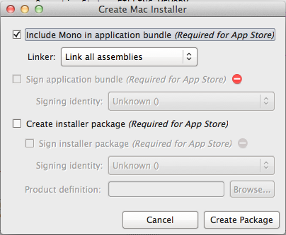
When developing applications with Mono/MonoMac it is very useful to create an installer that bundles Mono with your application. MonoMac includes a utility for creating an installer but unfortunately it is bug ridden and limited. Here are the steps that work for me.
Note: make sure you have Xcode installed.


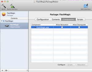
You may or may not want to uncheck the option to allow relocation. On your development Mac if you don’t uncheck this then the installer will find a version of your application inside your MonoDevelop solution and overwrite it rather than putting it into /Applications. This makes it appear as if the installer didn’t work. On non-development Macs this option allows the application to be overwritten even if the user has moved it after installing an older version.
Sep 24th
When developing for C# and using Windows Forms creating and using global objects is trivial:
public static class Program
{
  public static Foo MyFoo = new Foo();

  static void main()
  {
    Main = new MainForm(MyFoo);
  }
}
The same can’t be said for MonoMac. The mistake is to equate the static MainClass class as being the same as the WinForms Program class in the example shown.
The solution is to put the global class instantiation inside the NSApplication delegate. MonoMac creates this automatically and calls it AppDelegate. The above example becomes:
public partial class AppDelegate : NSApplicationDelegate
{
  MainWindowController mainWindowController;

  public Foo MyFoo = new Foo();

  public AppDelegate ()
  {
  }

  public override void FinishedLaunching (NSObject notification)
  {
    mainWindowController = new MainWindowController(MyFoo);
    mainWindowController.Window.MakeKeyAndOrderFront(this);
  }
}