Interesting Tech Projects
Using Alibre Design for 3D Printing of Multi-Part Projects
The easiest way to design projects that involve multiple parts in Alibre Design is to create and edit parts inside an assembly workspace. This allows the edges and cross-sections of one part to be reused in another part which is very useful.
However for 3D printing there is a downside – creating a part inside an assembly results in that part being orientated the same way in the part workspace as it in the assembly workspace. For 3D printing we want a specific side face down on the XY plane. That choice of side depends on the part.
So we have taken advantage of the tools and features that Alibre Design offers but we now have parts that are not orientated correctly for printing. They can be rotated in Alibre Design by creating a new assembly just for that part but there must be an easier way.
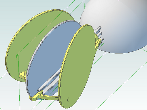
The following screenshot illustrates the problem. The circular panel is in an assembly and orientated the way we need it to check that everything fits together.
Opening the part in it’s own workspace shows the orientation.
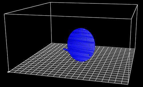
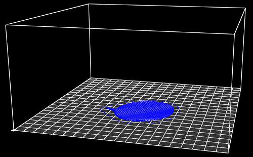
Exporting and slicing this part as it is results in the following g-code.
So how can we make this easier, especially if we have an assembly with lots of parts? By using an add-on for Alibre Design.
I’ve updated my AD Assembly Exporter utility that I have previously written about. It can now automatically rotate STLs when they are exported so that the desired face is aligned with the XY plane.
First you must choose the face that will be placed on the print bed.
- Edit the part
- Right-click on the face and choose Insert Plane..
.
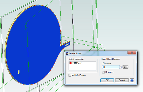
- Click on OK
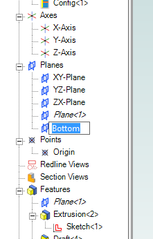
- In the Design Explorer right-click on the new plane and choose Rename
- Enter the name “Bottom”
Now save the part and open the assembly containing it, if it wasn’t already open. Repeat this for all parts in the assembly that will be printed.
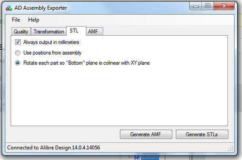
Run AD Assembly Exporter, click on the STL tab and choose the option to rotate using the “Bottom” plane.
Then click on Generate STLs. Here is the new g-code output:
| Print article | This entry was posted by Andy on March 13, 2013 at 2:46 pm, and is filed under 3D Printing, Software Engineering. Follow any responses to this post through RSS 2.0. Both comments and pings are currently closed. |
Comments are closed.
