BritishIdeas
Interesting Tech Projects
Interesting Tech Projects
Mar 22nd
I decided that the McWire CNC machine probably wouldn’t be able to product the accuracy I need, or have the lifespan that I need for a machine. In addition I want to be able to cut objects up to a square foot in size. The McWire design would need to be four square feet in size to be able to do that. Instead I decided to buy a machine kit.
I was drawn to the Fireball CNC designs because they are individually hand made and affordable. They also use a gantry design which results in a footprint not much larger than the cutting size. The problem was that they didn’t make a machine that could cut one square foot objects. Until now that is…
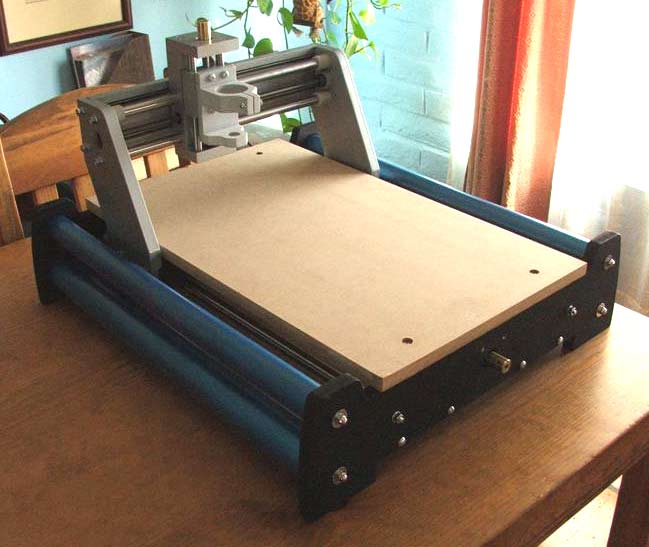
Fireball CNC have just released the V90, which has a cutting area of around 12″ x 18″ x 3″. I was fortunate enough to get one during the beta testing phase. Below is a picture of the assembled machine.
The next steps are to extend the motor wires, attach them and test jogging from EMC2.
Feb 27th
This post contains some step by step instructions on getting started with free Flash development using the Flex 3 SDK and FlashDevelop, both free.
I noticed that the getting started tutorials on the Adobe website are aimed at people who have purchased the Flash Builder package, so skip over some of the important details required for using the free Flex 3 SDK. This post is an adaptation of Getting Started With Flex Development And Why Its Worth Learning.
Next we need to get FlashDevelop, which is a great, and free, IDE for Flash Development.
Now you can follow the rest of the short tutorial at Getting Started With Flex Development And Why Its Worth Learning starting with the point where a new ActionScript file is created. Within minutes you will have your first flash script built with debug output!
Feb 2nd
Recently I needed to restore a backup made with Acronis True Image, however when I booted using the True Image recovery CD it didn’t work. Instead of restoring the image it rebooted the PC. Not very helpful.
After a bit of research it turns out that Acronis uses Linux for their recovery CD and sometimes this has problems with the hardware. An alternative is to use a free tool to create a Windows based recovery CD that runs True Image. The software is called BartPE.
Download BartPE (PE Builder) and install it.
If you have Acronis True Image 10 then you already have the BartPE plugin. If you have Acronis True Image 11 then I believe you have to register your copy and log into the Acronis site for the free download. For True Image 10, go to C:\Program Files\Acronis\TrueImageHome and rename the BartPE folder to “AcronisTrueImage”.
Copy the AcronisTrueImage folder to the “plugin” folder inside the BartPE installation folder. In my case that meant copying it to C:\pebuilder3110a\plugin
Run PE Builder from the Start menu.
Select the location where your Windows installation files are
Click on “Plugins” and make sure that Acronis True Image is enabled (should be by default).
Choose desired media output.
Click on “Build”.
This will either generate an ISO file for burning to a CD or burn the CD for you (depending on the options you choose).
Next, boot your PC with the BartPE CD inserted. Once you have gone through the network options, Acronis True Image can be found on the Go menu at:
Go -> System -> Storage -> Acronis True Image
Jan 11th
The project was paused for Christmas and New Year, now I’m wondering whether to continue with the McWire design or go with something else. I recently came across the Fireball CNC machine, which looks very nice. Each machine is hand made in the US, which appeals to me.
One of the early projects I wish to work on is a clock and I found some nice clocks with plans for sale. I contacted the designer and the largest part in the design I am interested in is a cog with a diameter of 11 1/2″. This is too big for the Fireball CNC machine.
So, looking at the McWire design, in order to cut parts 12″ by 12″, the machine would need to have a footprint of at least 24″ x 24″. The design isn’t a compact one. So I am currently undecided what to do. Unless I find a design that really looks appealing I may continue with the McWire design.
My recommendation for anyone wanting to build a CNC machine is to think carefully about how large the parts are that they want to make, then pick a design that fits that requirement.
Dec 26th
I wanted an easy way to resize images for email after importing them from a digital camera when using Gnome. Gnome by default uses gThumb for the import and it seems like an easy to use program. The problem is that in order to resize images several mouse clicks are needed, followed by a file rename.
So I wrote this quick little script to perform the resizing for me. Note that it only works with one picture at a time. To install copy to somewhere like /usr/share/scripts and make sure it is executable by everyone (sudo chmod 755 /usr/share/scripts/resizeimage). Then in gThumb go to the preferences and click on the Hotkeys tab. Add the following to one of the hotkeys (I used zero):
/usr/share/scripts/resizeimage %f %n %e
Then in gThumb select an image and press the hotkey (on the numeric keypad). The image will be resized and renamed in one step.
The script is written to resize the image so the longest side is 800 pixels, while maintaining the aspect ratio. You need to have ImageMagick installed. If the original image is called foo.jpg, then the resized image will be called foo.resized.jpg, just like the Nautilus Image Converter does.
#!/bin/bash

# resizes an image for email, preserving aspect ratio

# requires imagemagik

# call: resizeimage /home/andy/foo.jpg /home/andy/foo .jpg

# in gthumb: resizeimage %f %n %e
convert "$1" -resize "800x800>" "$2.resized$3"
Nov 27th
I’ve found what looks like a good source for bearings for the design. It’s Skate Bearings and they sell individually as well. Price seem very reasonable. If I can’t find a local skate shop then I will probably order from them.
Nov 23rd
The Yahoo group for the HobbyCNC boards contains a file which describes a linear, unregulated 10A power supply, suitable for driving four motors. This power supply converts 120VAC to 34VDC up to 10A. The circuit diagram is very simple, but a lot of additional effort and parts are required to construct a working power supply.
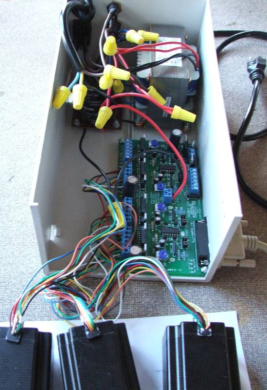
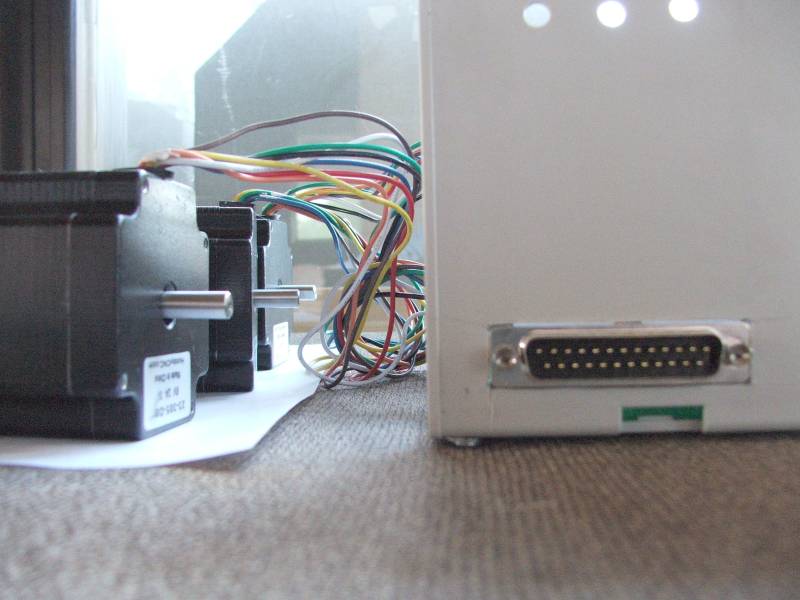
Here is a picture of my completed power supply connected to three motors:
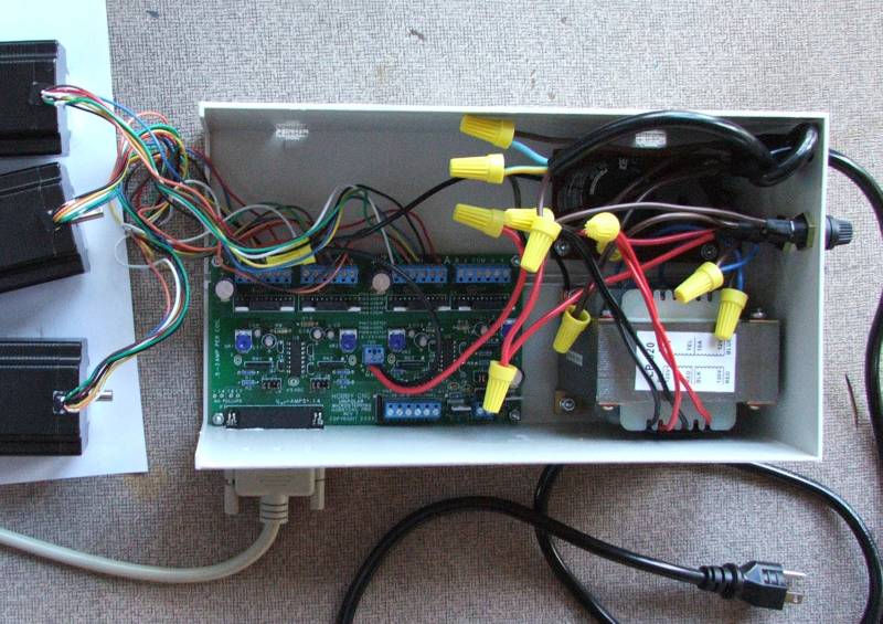
As you can see, the power supply sits in a box with the HobbyCNC board. Currently the lid is missing, as are the ventilation holes. Also the motors are simply connected to the board rather than via eight conductor cable that goes through holes in the side of the case.
I am not going to reproduce a circuit diagram here because I don’t want the liability issues of publishing a circuit diagram that involves lethal voltages. If you own a HobbyCNC board then you can get the circuit diagram (and warnings) from the files section of the Yahoo group, otherwise you can find plenty of designs using Google. In general however the power supply should match the requirements of the control board you are using, and the vendor of the control board should be able to suggest a ready-made power supply or a circuit diagram for one.
All information in this posting is for reference only. Anyone who uses this information assumes all risks. The voltages involved can kill and all necessary precautions should be taken. In addition a large capacitor is used which can keep the voltages high for a period after the power is turned off. The power supply should not be run with the lid off and all exposed metal parts inside and outside of the power supply should be grounded. For this reason I chose to use a grounded power cable rather than the cheaper two prong design. If you are not proficient with using mains voltages you are better off just buying a suitable power supply. I do not claim or guarantee that any parts I have used are suitable for this purpose. All information is provided “as is” and without waranty. Y0u have been warned…
The power comes in to the board via a standard power cord and is connected through a 4A fuse to a rocker switch. After the rocker switch is the 10A transformer than produces 24VAC. This is then fed into a AC to DC converter board to produce 34VDC. The DC voltage then goes through a 10A fuse to the HobbyCNC board.
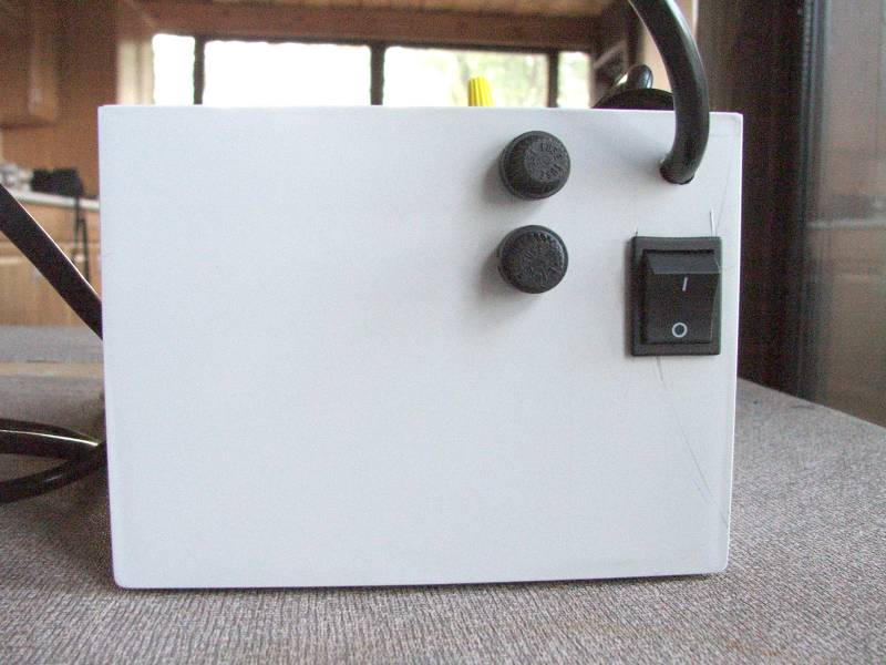
Here is a view of the rocker switch and the two panel mounted fuse holders:
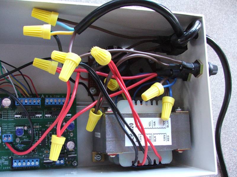
The transformer, AC to DC board and the HobbyCNC board are all bolted down to the bottom of the case using bolts. I added 1/4″ spacers below each to lift the boards up off the bottom of the case. I positioned the HobbyCNC board up against the edge of the case and cut a rectangular hole for the PC connector. This fits snugly giving a nice finish:
The AC to DC board is made of stripboard (prototype board with copper strips), and contains the recitifer, capacitor and resistor. I wanted to make the construction modular so I used wire connectors to connect the various components (transformer, AC to DC board, fuses, switch, HobbyCNC board, power cord) together. This allows me to easily replace any component when needed.
Still to do is the lid, an emergency stop switch and some ventilation holes.
Bill of Materials (read the disclaimer at the start of this post!):
1x 24V 10A Transformer LP-520, MPJA.com #7846TR, $17.99
1x 27000uF Electrolytic Capacitor, Digi-key #P10021-ND, $11.72
1x 2kOhm, 1W 5% Metal Oxide Resistor, Digi-key #2.0KW-1-ND, $0.15
1x 35A, 600V Bridge Rectifier Wire Leads, Digi-key #MB356W-BPMS-ND, $5.00
1x DPST 16A Rocker Switch, Digi-key #CH784-ND, $1.46
1x 16AWG 3 Conductor Power Cord 79″, Digi-key #Q110-ND, $5.43
2x 3AG Panel Mount Fuseholder, Digi-key #F005-ND, $6.10
1x 4A 250V Fuse, Digi-key #283-2023-ND, $0.48
1x 10A 250V Fuse, Digi-key #283-2622-ND, $0.57
1x 14AWG Wire Red 2ft, Local, $0.46
1x 14AWG Wire Black 2ft, Local, $0.46
1x 14AWG Wire Brown 2ft, Local, $0.46
1x Heat Shrink Tubing Assorted Sizes, Local, $2.99
4x #4 x 3/4″ Bolt, Local (Ace Hardware), $0.28
4x #4 Nut, Local (Ace Hardware), $0.24
4x #4 Washer, Ace Hardware), $0.24
4x #4 1/4″ Spacer, Local (Ace Hardware), $2.32
8x #6 x 3/4″ Bolt, Local (Ace Hardware), $0.56
8x #6 Nut, Local (Ace Hardware), $0.48
8x #6 1/4″ Spacer, Local (Ace Hardware), $2.32
15x #6 Washer, Local (Ace Hardware), $0.90
1x #6 External Tooth Washer, Local (Ace Hardware), $0.08
1x Stripboard, Local, $3.49
1x 20 Pack Wire Connectors 600V, Local (Home Depot), $1.99
Total cost: $66.17
Not included: soldering iron, solder, shipping costs, taxes on local purchases.
Note that the shipping cost for the transformer was $10.51.
The total cost including taxes and shipping was probably closer to $85. A ready-made power supply can probably be purchased for $110 plus shipping, so perhaps it didn’t save very much.
Missing from the list is the case. That is because I managed to salvage an old index card drawer and holder. I threw the drawer away and carved up the holder to make the case. This cost me $2 from World Care. A brand new plastic case will cost around $30 from Digi-key or Mouser.
The cost of the power supply is not insignificant. When people post low cost CNC designs they love to indicate how cheap the project is but omit important details like the power supply. If you want motors with a good amount of torque then a good sized power supply is also required.
Nov 19th
After spending quite some time trying different pieces of software I have come up with a collection and a workflow that I think will fit my needs.
I wanted to be able to accurately design parts in 3D, see how the parts will fit together to make sure they are right, and produce traditional engineering drawings of the parts, if possible. Also it is necessary once a part has been designed to be able to convert it into toolpaths, which is the path that a drill bit would move along to make the part. The toolpaths are represented using g-code which can be processed by EMC2 to move the stepper motors. Another requirement was to use free software where possible to try and keep costs down.
I start with Alibre Design Xpress. This is an excellent 3D design program that is also free. However free comes with a price, that is limitations. The key limitations are a limited number of export options and limited number of parts in an assembly. An assembly is a collection of parts fitted together to build something. However with enough perseverance these limitations can be overcome. In Design Xpress I created a simple test part that contains two holes for bolts:
Creating this 2D profile is very quick and easy. The holes are 0.174″ in diameter, which should be big enough for a #8 bolt. Next step is to extrude the 2D profile into a 3D part:
The part can be rotated and viewed from any angle. I decided to make the part 0.250″ thick. At this point Design Xpress can produce various numbers regarding the part, depending on the material it is made of. Choosing “Wood – southern pine” resulted in:
Volume = 1.480147117 in³
Mass = 1.576592260E-2 kg
Surface Area = 1.453202145E1 in²
Pretty interesting.
The software only allows five unique parts in an assembly, unless you register then it is 10. However this is quite a severe limitation in my opinion. Fortunately there is a way around this. Alibre has written an add-on called 3D Publisher for Google Sketchup that allows parts to be exported in Google’s Sketchup format. It’s not a requirement that the parts be uploaded to Google’s 3D Warehouse. Instead the exported parts can be saved to your hard drive. The following screenshot shows an assembly of two of the test parts along with size #8 bolts and nuts. The exact bolts are ANSI PHN, CRSHD TYPE II, B18.6.3, .164-36 UNF, 0.75, which gives an indication of the accuracy expected from designing parts and assembling them.
Again, this assembly can be rotated and the parts can be made transparent, along with plenty of other options. There is even a free add-on for Google Sketchup that provides a ray tracer. Assembling two parts confirmed my intention that the holes will line up.
With a few mouse clicks Design Xpress can convert the 3D part into traditional engineering drawing:
This can be printed out, emailed, etc. and provides all the measurement details for someone else to reproduce the part without having access to electronic files. The drawing can also be exported as a DXF (without the annotations), which is needed for the next step.
I found an excellent application to generate toolpaths for a part called CamBam. It takes a DXF file and provides an easy to use user interface in which you can select which items are profiled, drilled, pocketed, etc. Once the DXF file is loaded into CamBam all the unneeded views are deleted to leave the original 2D profile. For this part I added a 2.5D profile operation to cut the outline of the shape and two sprial drill operations for the holes:
Cam Bam then generates the g-code which can be loaded in the AXIS interface in EMC2:
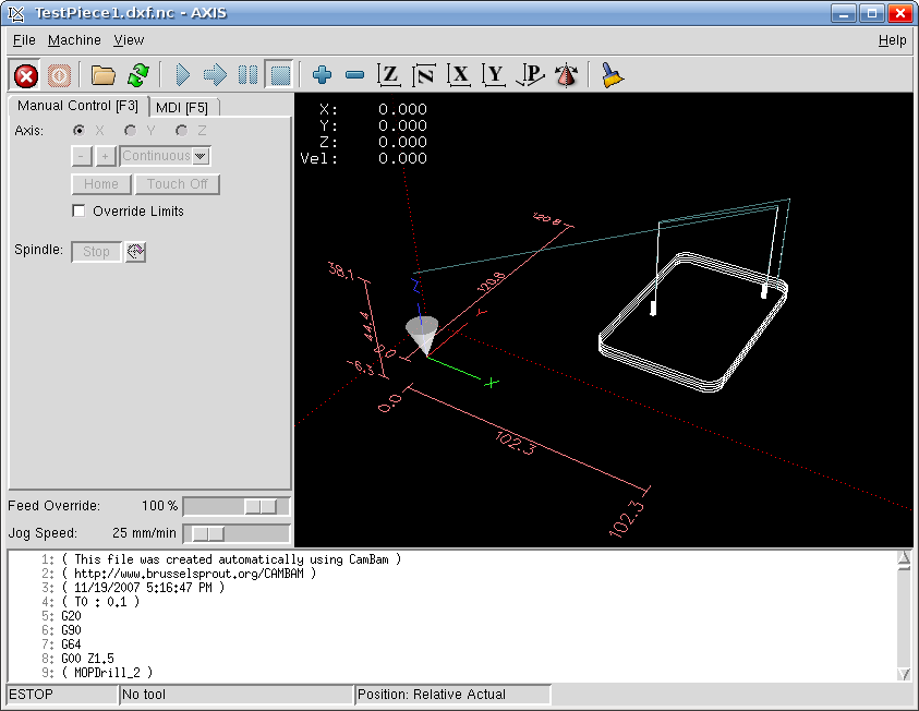
This process may seem convoluted, and it requires both Windows and Linux, but all the software can be obtained for free and is high quality. I haven’t completed my CNC machine yet, but I can watch the part being made in the AXIS interface without having the motors connected. I would expect that all the software will work in a Virtual Machine in Linux, however note that Design Xpress requires a lot of RAM to run (300Mb I believe).
Nov 12th
I have stumbled across a large list of low cost and free CAD programs, mostly for Windows however. It seems there are many good choices in the list and I will try out a couple in the next day or two.
Nov 7th
April 2008 – Update – I’ve modified the instructions so that EMC2 can now be run as a user.
April 2008 – Update – Fixed some mistakes.
The following instructions will describe how to install the latest version of EMC2/LinuxCNC in Ubuntu 7.10 Gutsy Gibbon.
Why would you want to do this? You would do this if you don’t want to wait for new .deb files from the EMC2 team or you want to install EMC2 in the latest version of Ubuntu to take advantage of all the new features. The alternative is to use the Ubuntu 6.06 LTS live CD, install and then either stick with the software versions supplied or upgrade to the latest versions (such as device drivers, Gnome, Xorg, etc.), which is a big task itself.
Why would you not want to do this? I don’t recommend following these steps if you are unfamiliar with Linux and the shell/command prompt. It will either be a great learning experience or a very frustrating waste of time.
I am sure these steps can be simplified and improved, however they were created from many hours of experimenting and following dead-ends. I wanted to try and give you exactly what I ended up using, rather than an optimization. For example I’m sure that not all the reboots are needed, but they only take 60 seconds on my PC anyway.
These steps should work on a stock installation of Ubuntu 7.10, however I don’t make any claims that they will work for anyone else. If the software didn’t install correctly and the motors go crazy and move something that destroys your house, don’t blame me – these instructions are provided “as is” and without any warranty. Use at your own risk. If you spot a mistake please let me know and I will update the instructions.
Where you see “andy” replace with your own username, unless it is also “andy”. 🙂
‘$’ represents the prompt, to show you where the start of lines are. Don’t enter this, just what follows.
The process looks like this:
Get a vanilla kernel and patch it with RTAI support.
Test kernel.
Build and test RTAI modules.
Build EMC2.
Enable universe repository in /etc/apt/sources.list. Open a terminal window and then:
$ sudo apt-get update

$ sudo apt-get install build-essential libncurses5-dev kernel-package

$ cd /usr/src

$ sudo wget -c http://www.kernel.org/pub/linux/kernel/v2.6/linux-2.6.22.tar.gz

$ sudo tar xzvf linux-2.6.22.tar.gz

$ sudo mv linux-2.6.22 linux-vanilla-2.6.22

$ sudo ln -s linux-vanilla-2.6.22 linux

$ cd linux

$ sudo cp /boot/config-2.6.22-14-generic .config

$ sudo make menuconfig
At this point a menu will appear. Make the following choices:
Loadable module support > Module versioning support (N)
Loadable module support > Set version information on all module symbols (N)*
Processor type and features > Preemption model > Preemptible kernel (low latency desktop)
Processor type and features > Symmetric multi-processor support (N)**
Processor type and features > Local APIC support on uniprocessors (N)
Power management options (ACPI, APM) > ACPI support (N)
Power management options (ACPI, APM) > APM BIOS support (N)
Power management options (ACPI, APM) > CPU frequency scaling (N)
Kernel hacking > Compile the kernel with frame pointers (N)
* only if you have it in the menu
** only if your PC is not dual or quad core
Download rtai-3.6-test1.tar.bz2 from www.rtai.org (click on “RTAI Repository” link) to the desktop.
$ cd /home/andy/Desktop

$ bunzip2 rtai-3.6-test1.tar.bz2

$ tar xvf rtai-3.6-test1.tar
$ cd /usr/src/linux

$ sudo patch -p1 < /home/andy/Desktop/rtai-3.6-test1/base/arch/i386/patches/hal-linux-2.6.22-i386-1.10-09.patch
$ sudo make-kpkg --initrd --revision=1 --append-to-version=-realtime kernel_image kernel_headers
Some questions may appear which need to be answered (answer Y to any others that appear):
Interrupt pipeline – Y
Interrupt pipeline maintain backwards compatibility – Y
Interrupt pipeline debug – N
Now go and do something else for a while. On my P4 1.6GHz PC the kernel took 2 hours and 50 minutes to build.
$ cd ..

$ sudo dpkg -i linux-image-2.6.22-realtime_1_i386.deb

$ sudo nano -w /boot/grub/menu.lst
Find the line that looks like:
hiddenmenu
and change it to:
#hiddenmenu
If your PC already dual-boots (for example Ubuntu and Windows) then the hiddemenu is probably already commented out (using the ‘#’).
Save and exit nano.
Reboot and choose the realtime kernel from Grub menu.
Enter:
$ uname -a
and you should get something like:
Linux pepper 2.6.22-realtime #1 PREEMPT Sun Oct 28 10:54:43 MST 2007 i686 GNU/Linux
Make sure everything works ok (browsing, editing files, etc.)
Now we need to build the RTAI modules. This has to be done while running the realtime kernel we just built and booted into.
$ cd /home/andy/Desktop/rtai-3.6-test1

$ make menuconfig
Again a menu appears. Make the following selections:
Machine (x86) > Number of CPUs (enter the number you have here)
Exit and save configuration
$ make

$ sudo make install
Reboot back into the realtime kernel.
$ cd /usr/realtime/bin

$ sudo nano -w rtai-load
Change the first line from:
#!/bin/sh
to:
#!/bin/bash
and save. Then:
$ sudo nano -w /etc/init.d/create-rtai-devices.sh
Enter:
#!/bin/bash

mknod -m 666 /dev/rtai_shm c 10 254

for n in `seq 0 9`

do

f=/dev/rtf$n

mknod -m 666 $f c 150 $n

done
Save. Then:
$ sudo chmod 755 /etc/init.d/create-rtai-devices.sh

$ sudo update-rc.d create-rtai-devices.sh defaults
Reboot back into the realtime kernel.
Then test the RTAI support with:
$ cd /usr/realtime/testsuite/user/latency

$ sudo ./run

$ cd /usr/realtime/testsuite/user/preempt

$ sudo ./run

$ cd /usr/realtime/testsuite/user/switches

$ sudo ./run

$ cd /usr/realtime/testsuite/kern/latency

$ sudo ./run

$ cd /usr/realtime/testsuite/kern/preempt

$ sudo ./run

$ cd /usr/realtime/testsuite/kern/switches

$ sudo ./run
These tests spit out lots of numbers. The thing we are looking for here are kernel panics, system crashes, etc. Also make sure there are no overruns in the tests that display an overruns column.
If you get something like:
insmod: error inserting '/usr/realtime/modules/rtai_hal.ko': -1

Operation not permitted
then try:
$ sudo nano -w /boot/grub/menu.lst
and find the kernel line for the realtime kernel. Add “lapic” to the end of it and reboot, then run the tests again. For example:
kernel /boot/vmlinuz-2.6.22-realtime root=UUID=45d21232-cf0d-cc3d-87ce-8453214d7a6f ro quiet splash vga=794 lapic
Once you have the real time tests working continue with:
$ sudo nano -w /etc/modprobe.d/emc2
Enter:
install parport_pc /bin/true
Save then reboot back into the realtime kernel. Now to build and install EMC2.
$ sudo apt-get install python python-imaging python-imaging-tk python-numarray python-dev

$ sudo apt-get install tcl8.4-dev tk8.4-dev yapps2

$ sudo apt-get install libgtk2.0-dev libpth-dev libreadline5-dev libxmu-dev libxaw7-dev libglu1-mesa libglu1-mesa-dev libgl1-mesa-dev

$ sudo apt-get install pciutils-dev bwidget cvs latex2html preview-latex-style libaiksaurus-1.2-0c2a libgnomeprintui2.2-dev

$ sudo apt-get install imagemagick lyx
$ cd /usr/src

$ sudo dpkg -i linux-headers-2.6.22-realtime_1_i386.deb

$ cd ~

$ cvs -z5 -d:ext:anon@cvs.linuxcnc.org:/cvs co emc2

$ cd emc2/src

$ ./configure --with-realtime=/usr/realtime --with-kernel-headers=/usr/src/linux-headers-2.6.22-realtime

$ make

$ sudo make install
$ sudo nano -w /etc/security/limits.conf
Add the line:
* hard memlock 20480
Save and reboot into the realtime kernel.
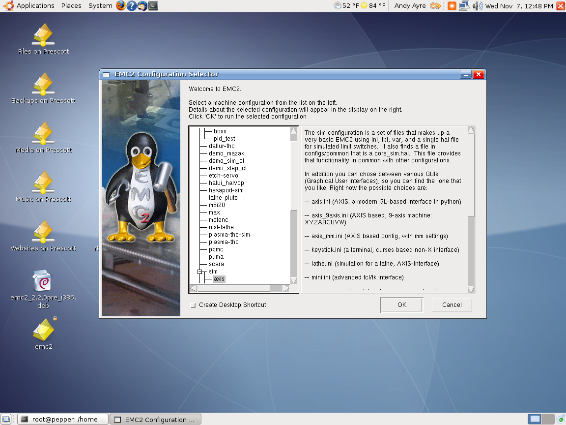
To run EMC:
$ /usr/local/bin/emc
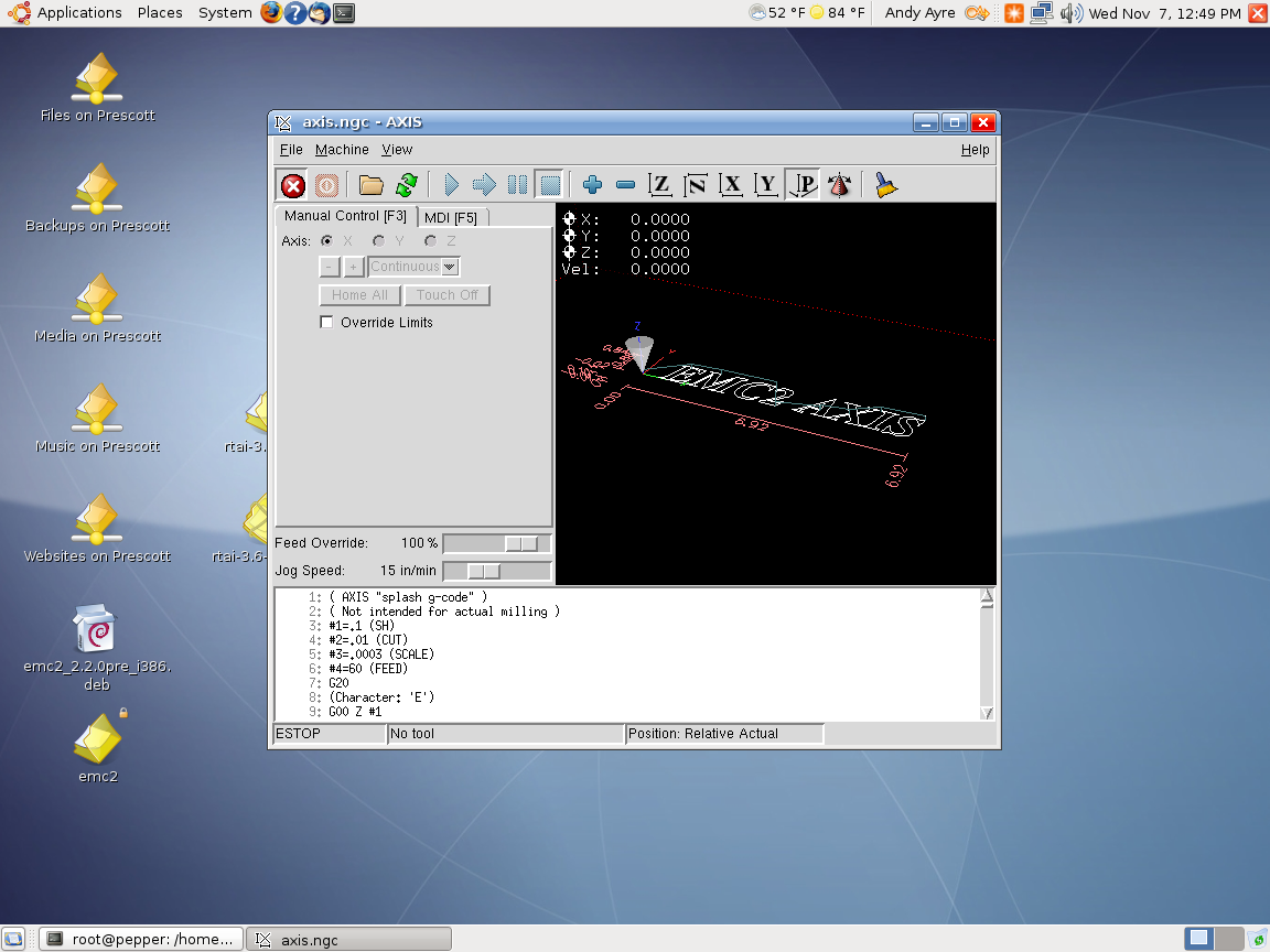
A window should appear with a choice of configurations. Choose Axis -> Sim and the Axis window should open. Congratulations EMC2 is now running!
Note that when running the realtime kernel the computer may not power itself off when the shutdown option is chosen. This is because the power management options have been disabled in the kernel. On my PC I wait a couple of minutes after the screen goes blank then press the power button on the front of the PC. This turns it off.